 главная · контакты · книги главная · контакты · книги
|
Microphoto attachment МФН-12 (MFN-12)
|
| Limits of the dioptrical focusing of the eyepiece, dptr | ±5 |
| Huygens eyepiece 7x (focal distance / visual field), mm |
36 / 18 |
| Compensation eyepiece 10x (focal distance / visual field), mm |
25,2 / 13 |
| Size of frame, mm | 24x36 |
| Overall dimensions, mm | 140x145x260 |
| Massa, kg | 1,4 |
3. DESIGN AND OPERATION
3.1. Optical Schema
Rays of light coming from photoeyepiece 1 (fig. 1) are divided into two pencils with prism 2. The major part of the light flow (about 60%) passes through lens 2 onto photofilm 3. The rest part is reflected from the prism at 20° and directed in the eyepiece 4 of the visual tube.
Lens 5 of the visual tube brings the reflexion of the object onto the plane of grid 6 placed in the focal plane of eyepiece 4. Grid 6 is installed in such a way that the reflexion of the object image is got sharp as on the photofilm as well as on the grid.
Eyepiece 4 of the visual tube can be shifted within ±5D for focusing onto the grid in accordance with eyes. The rectangular (film gate) and four double lines are put down on the reticle. They serve for more accurate focusing of the eyepiece.
Optical scheme of the attachment is made so, that the part of the reflexion of the object image limited with the film gate in sight of the visual tube is fully placed on the film in the frame of 24mm x 36mm.
3.2. Design
General view of the microphoto attachment is given in fig. 2.
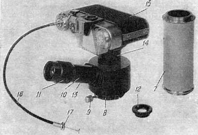
General view of the microphoto attachment is given in fig. 2.
Vertical tubus 7 is installed in the recess under the eyepiece tubus so that the eyepiece bush is to be set from upwards.
The low setting flange of attachment's body 8 is placed on the upper conical boring of tubus 7 and is fixed with screw 9.
Light-dividing prism 2 (fig. 1) is fixed in the body of the attachment.
Inside visual tube 10 (fig. 2) lens 5 (fig. 1), grid 6 and eyepieces 4 are placed.
When dioptrical bush 11 (fig. 2) is turned taking hold on its knurling the eyepiece is shifted along the thread with respect to the optical axis Tor adjustment of it on sharpness of the grid.
Smoke-coloured light filter 12 is put on the eyepiece for protection of eyes from the bright light when looking into the visual tube.
Screw 13 serves for adjusting of the grid at the plant-manufacturer, that's why it can be unscrewed in no case due to the shifting of the grid. The grid is put in such a way that the sharp reflexion of the object image is got simultaneously as on the grid as well as on the film.
Camera 15 with cable release 16 screwed into it is fastened to barrel 14 on the attachment housing. In contrast with the standard cable release, cable release 16 has a device which helps to make the shutter, set to the exposure «B», be automatically open during a long period of time. If washer 17, the tail of which is inserted into the cable release head, is pressed against the cable release head and slightly turned clockwise, the cable release will operate as standard one. If the washer is turned counterclockwise, the knob will not return to the initial position after being pressed and the shutter exposure «B» becomes a long exposure. Only after additional pressing washer 17 the cable release knob returns to the initial position and closes the shutter.
4. MARKING
Every attachment bears the following designations: Manufacturer's trade mark, symbol and item number. The first two digits of the item number stand for the two last digits of the year of output.
5. OPERATION PROCEDURE
Correct adjustment of illumination and proper opening of field and aperture diaphragms are of considerable importance for microscope resolution and quality of photos, so it is necessary to adjust the microscope carefully before photographing.
5.1. Simultaneous Observation and Photographing
During assembling of the attachment and installation of it on the microscope, the inclined tubus is taken from the microscope and the vertical tubus 7 is put on its place. An eyepiece from the set is inserted in the upper plug of the tubus 7. Body 8 of the attachment is to be installed on the upper conical boring of the tubus and then to be tightened with the screw 9.
For work with the microphoto attachment first of all the microscope must be adjusted according to the description of the microscope; by way of rotating of dioptrical plug 11 the eyepiece of the visual tube of the attachment is set for sharp reflexion of the grid in accordance with the eye. In this case the reflexion of the grid is considered to be sharp if an observer sees the reticules of the grid separately and clearly.
Then, watching in the visual tubus of the attachment, the microscope is focused onto the object by means of coarse and micrometric focusing.
Sharpness of reflexion image of the field stop is to be checked up. The best lightening of the object and the resolution of its structure are to be obtained. A light filter must be chosen and installed under the condenser of the microscope. As per the scale of exposure time of camera 15 the required rate of blow is to be installed, cable 16 is to be screwed in the camera, the shutter is to be cocked and photographing is to be started, following the description of the photographic camera.
5.2. Determination of Magnification
The magnification (Г) on the camera film is calculated from the following formula:
where Vob — linear objective magnification; Гoc — visual eyepiece magnification; 0,43 — adjustment coefficient.
Visual tube of attachment has proper magnification 2,5, hetherto visual observation magnification will be:
Example of calculation of magnification (objective 40X, eyepiece 10x):
Magnification on camera film Г = 40•10•0,43 = 172,
Magnification at visual observation Гattach. = 40•10•0,43•2,5 = 430.
Object-micrometer is used for accurate determination of magnification.
6. CARE OF MICROPHOTO ATTACHMENT, STORAGE AND TRANSPORTATION
6.1. Care
The attcahment requires careful handling.
The attachment should be wiped periodically with a soft rag soaked in acidless vaseline, then with dry soft clean rag.
Pay special attention to cleanness of optical parts.
Never touch the lens surfaces with fingers.
Dust the outer surfaces of lenses with a very soft brush washed in ether. For subsequent cleaning, if required, wipe them slightly with a soft, many times washed linen or cambric rag slightly moistened with benzine, anaesthetic ether or xylene.
6.2. Storage
Keep the attachment in dry, clean and warm premises.
Cover it, when inoperative, with a napkin or put it in its casing.
6.3. Transportation
For moving to another premises, put the attachment set into its wooden casing.
Take care that the attachment and its accessories never displace at shakes.
Any closed transport allowed.
7. CATALOGUE OF SPARE PARTS FOR EXTRA ORDER
| Huygenian eyepiece 7x | Ю-41.31.106 Сп |
| Compensation eyepiece 10х | Ю-41.31.504 Сп |
| Light filter СС1 | Ю-24.91.101 |
| Light filter ЗС11 | Ю-24.91.301 |
| Light filter ЖС12 | Ю-24.91.601 |
| Light filter ОС12 | Ю-24.91.801 |
| Light filter НСЗ | Ю-24.92.201 |
| Light filter НС8 | Ю-71.92.387 |
| Light filter НС10 | Ю-71.92.388 |
| Light filter in mount | Ю-41.59.211 |
| Vertical tubus | Ю-28.54.104 Сп |
Комментарии
| Игорь 78.25.122.2 28-06-2014 |
продам МФН-10 монокулярная ц,8000 и МФН-11 бинокулярная ц,14000 приборы новые в оригинальных деревянных ящиках с паспортами. г,СПб.(812)7864038 ; +79219445216 эл.п, [email protected] |
| © 2008-2023, Laboratorium.dp.ua — документация на лабораторное оборудование. | © Dr. Andy |
Авторство
Адрес: 49005, Днепропетровск, ул. Севастопольская, 17 (морфологический корпус ДГМА).
 контактная информация, написать сообщение

|